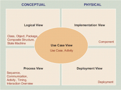
Architecture of software-intensive system can be described using multiple, concurrent views. Based on this fact Philipe Kruchten developed a view model consists of 5 views, that a software architect can look at a system. But why is this called 4+1 view model rather 5 view model ? The obvious reason is unlike four views one view shows the systems functionality from the view point of the outside world.
Following figure shows the 5 views, how they are related to each other and the diagrams used to explain each view.
Logical View
- Shows the parts that compromise the systems
- Represent a set of abstraction
- Emphasizes classes and objects
UML diagrams used
Class diagram
State diagram
Object diagram
State diagram
Object diagram
Process View
- Describes system processes
UML diagrams used
Activity diagram
Sequence diagram
Communication diagram
Implementation View (Development View)
- Illustrates a system from a programmer’s perspective
UML diagrams used
Component diagram
Deployment View (Physical View)
- Illustrates system execution environment
- Maps software artifacts to hardware that hosts them
UML diagrams used
Deployment diagram
Use Case View
- Illustrates system functionality
- Captures user goals and scenarios
- Helpful in defining the structure and functionality in other 4 views
UML diagrams used
Use case diagram

Hey, thanks for the blog.Much thanks again. Awesome.
Thanks for the feedback..:)
Interesting blog post. A few things i would like to add is that computer system memory needs to be purchased when your computer cannot cope with anything you do along with it. One can set up two RAM boards with 1GB each, by way of example, but not one of 1GB and one having 2GB. One should make sure the car maker’s documentation for own PC to make certain what type of memory is required.
v7Deye Im obliged for the blog article.Thanks Again. Awesome.
Major thankies for the post.Really thank you!
Thanks for sharing, this is a fantastic article.Much thanks again. Will read on…
Thanks-a-mundo for the article.Thanks Again. Cool.
ptAYPN Thank you ever so for you article post.Much thanks again. Awesome.
FRlySz Major thankies for the blog article.Much thanks again.
Very good article post.Really looking forward to read more. Keep writing.
WvA9gi This is one awesome post.Really looking forward to read more. Really Cool.
Q9RZuH Great article.Much thanks again. Will read on…
omESYM This is one awesome article post.Really thank you! Keep writing.